Assignment for week 13
- Add an output device to a microcontroller board you've designed and program it to do something
Board Designing
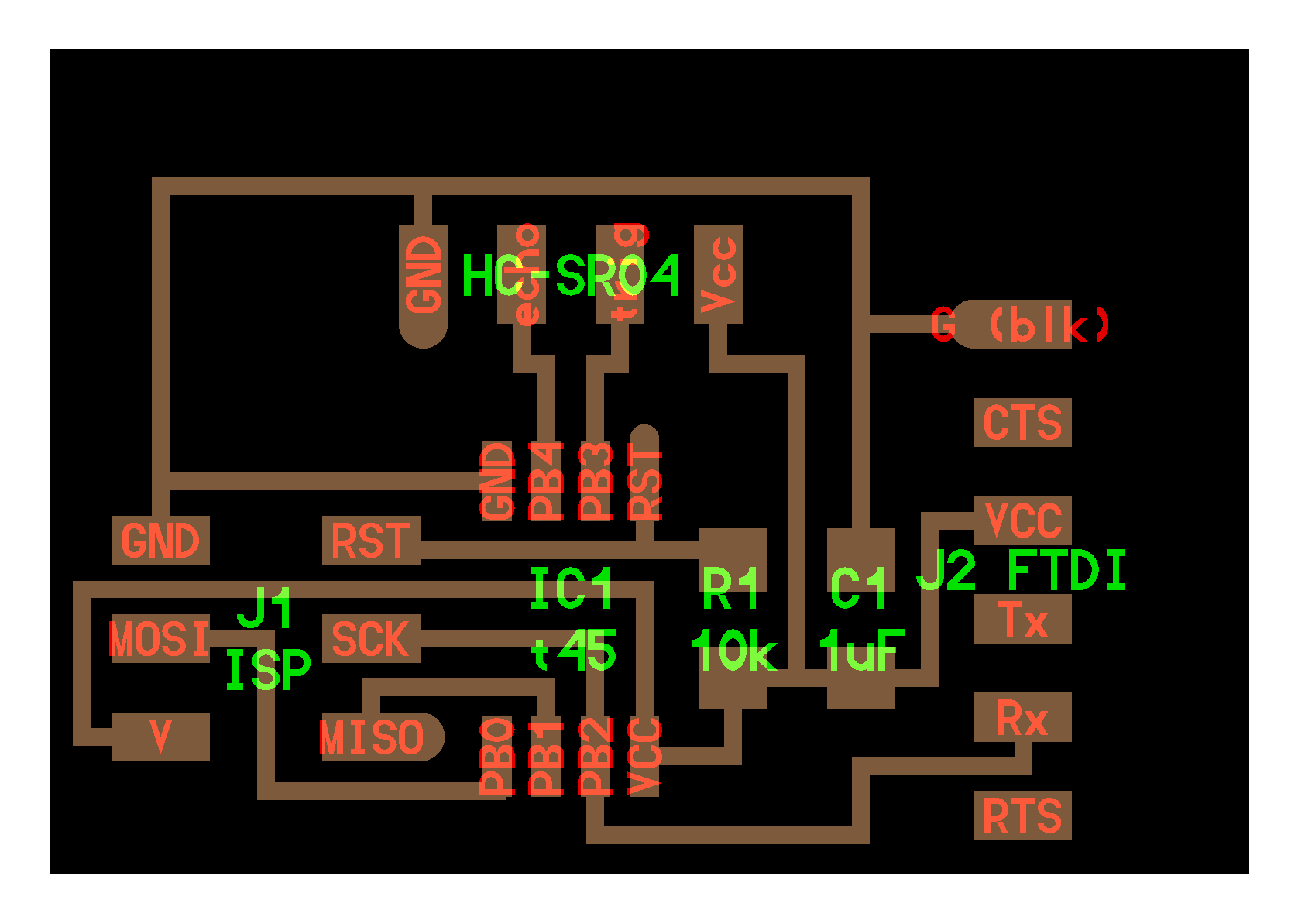
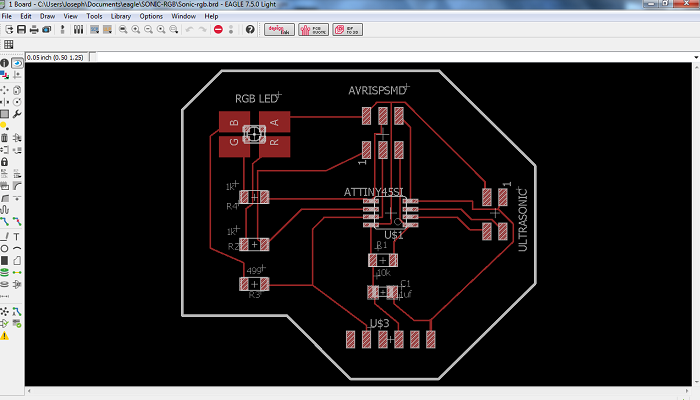
I have decided to design a the Input and Output circut in one board. I chosed the Ultrasonic Sensor "HC-SR04" as Input to be used in measuring the distance and "RGB Led" as Output for emmiting beautiful colors.
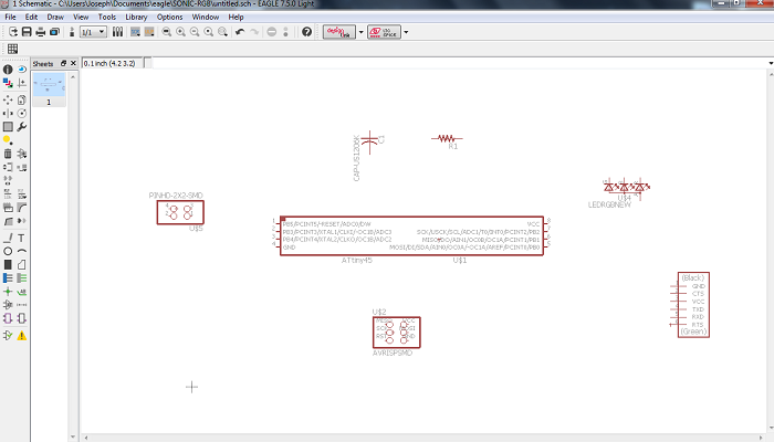
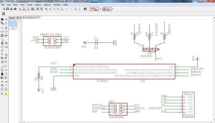
First I started form Niel's boards hello.HC-SR04 and hello.RGB.45 , and I used Eagle to combine them
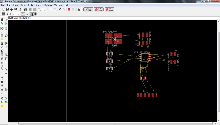
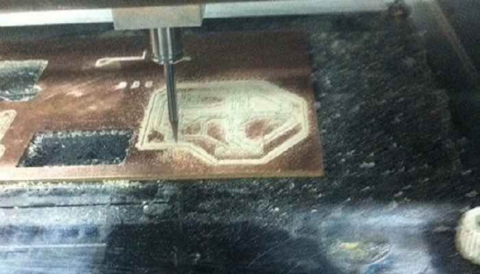
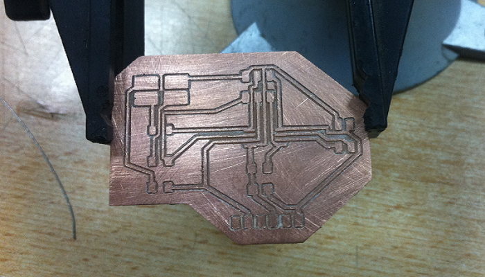
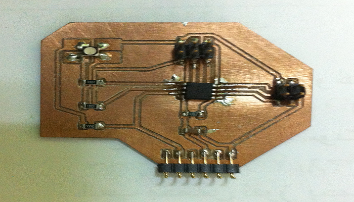
Machining and Soldering
Programming
This week I am focusing on the Onput part. I wrote a sketch to make the RGB blinking between "Red"-"Green"-"Blue" every 1 second.
                  int redPin = 0;
                  int greenPin = 1;
                  int bluePin = 2;

                  #define COMMON_ANODE
                  void setup()
                  {
                  pinMode(redPin, OUTPUT);
                  pinMode(greenPin, OUTPUT);
                  pinMode(bluePin, OUTPUT);
                  }
                  void loop()
                  {
                  setColor(255, 0, 0); // red
                  delay(1000);
                  setColor(0, 255, 0); // green
                  delay(1000);
                  setColor(0, 0, 255); // blue
                  delay(1000);
                ;
                  }
                  void setColor(int red, int green, int blue)
                  {
                  #ifdef COMMON_ANODE
                  red = 255 - red;
                  green = 255 - green;
                  blue = 255 - blue;
                  #endif
                  analogWrite(redPin, red);
                  analogWrite(greenPin, green);
                  analogWrite(bluePin, blue);
                  }
Fab Academy 2016 - Week 13 - Output Devices from Joseph Gourgy on Vimeo.

This work by Joseph Gourgy is licensed under a Creative Commons Attribution-NonCommercial 4.0 International License.